
GNC
November 2, 2026
Steering a rocket with its engine
Hopper has no fins and flies too slowly for aerodynamic control. Everything that keeps it upright comes from tilting one engine by a few degrees. This is how we sized that system before building it.
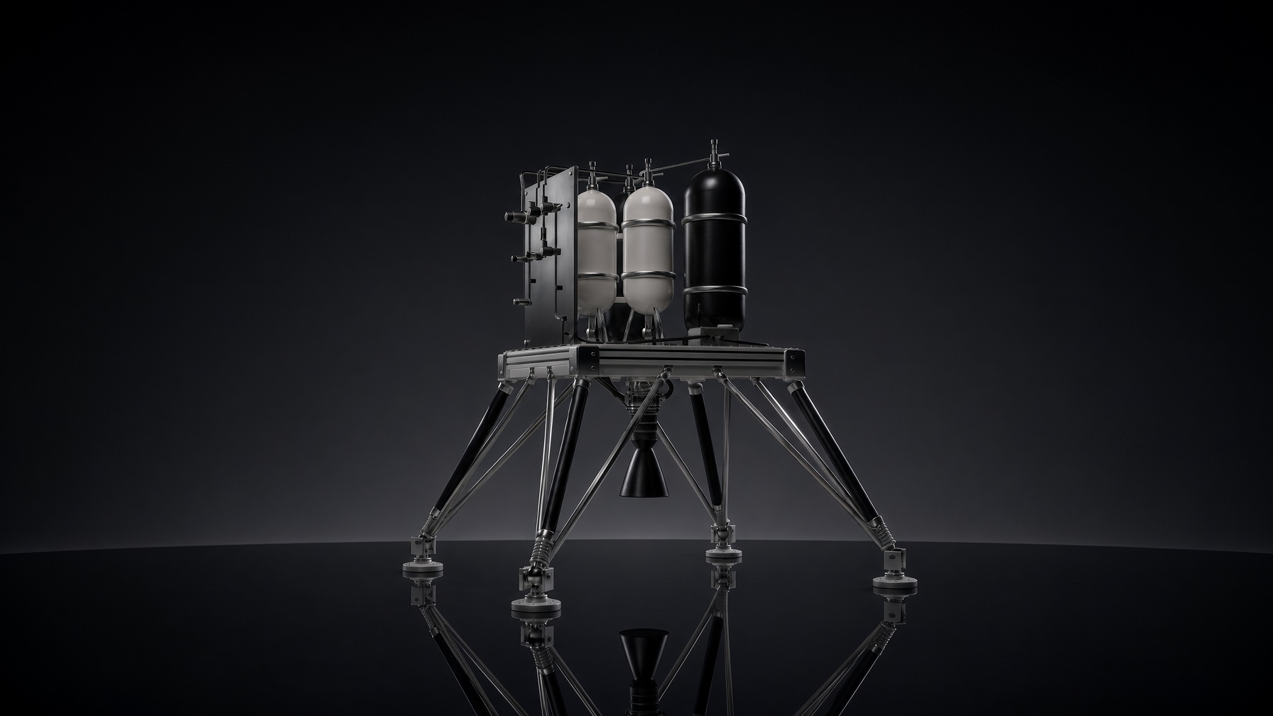
Hopper with the E2 engine mounted in its gimbal below the deck. Render.
The problem: one engine, no fins
A rocket that hovers and lands spends its whole flight at walking speed. At that speed fins produce no useful force, so the only thing that can rotate the vehicle is the engine. Hopper's E2 engine produces 2.2 kN of thrust and sits in a gimbal below the vehicle deck. Tilting it by one degree turns about 38 N of that thrust into a side force, and because the engine sits below the centre of gravity, that side force rotates the whole vehicle.
This is thrust vector control, or TVC. It is the single system that keeps Hopper upright from liftoff to touchdown, which is why we analysed it before cutting any metal.
How the system works
Two electromechanical linear actuators push and pull on the engine, one for each axis. Each actuator, called A10, combines a brushless servo motor with a ball screw. A motor driver closes the position loop locally, and the flight computer sends a new gimbal angle 200 times per second.
- Operating range: ±5° in normal flight
- Mechanical stops: ±8°, so the engine can never swing into the structure
- Pivot: 150 mm below the deck, which places the engine further from the centre of gravity and gives about 10 % more control authority than our earlier layout
How much is enough
The hard part of TVC is not making the engine move. It is knowing how far, how fast and against how much load it has to move. We answered that with a flight simulation of the complete vehicle that includes the things that actually disturb a hovering rocket:
- Wind gusts during hover and landing
- Uncertainty in where the centre of gravity sits
- Propellant sloshing in the tanks
- The stiffness of the propellant hoses that cross the gimbal
- Landing on a slightly sloped pad
We ran 150 randomised flights with these disturbances. In 99.7 % of them the engine needed no more than 2° of deflection and about 13° per second of rate to hold the vehicle within 3° of vertical. The worst single gust pushed this to 2.1° and 18° per second.
From simulation to requirements
Those results became the requirements for the actuator:
- At least 40° per second gimbal rate
- A closed-loop bandwidth of at least 10 Hz
- A design load of 25 N m at the gimbal, which includes hose stiffness, friction, offsets and the inertia of the engine
We then checked the requirements in the other direction: an actuator that meets exactly these numbers and nothing more still keeps the vehicle inside its tilt and position limits.
Where the margins are
The A10 has a large force margin, more than eight times the design load. Speed is where the margin is thin. With the current 2 mm ball screw on a 24 V supply, the actuator reaches about 51° per second under full load, which meets the requirement but not by much.
Two changes would each double that margin: a steeper ball screw with a 4 to 5 mm lead, or running the actuator at 48 V. The steeper screw has a second benefit. It reduces the motor inertia the engine sees, which lowers the load on the brackets if the actuator ever runs into its end stop.
What comes next
The actuators are now going through verification on the bench: stroke, speed, step response and stiffness under load. After that, the TVC system will be integrated with the engine for hot-fire tests at our test site in Aldenhoven, where the gimbal will move under real thrust for the first time.
Build this with us
Hopper is built by students from RWTH Aachen and FH Aachen. If you want to work on real rocket hardware, we would like to hear from you.
HOPPER
Hopper is a project of Space Team Aachen e.V., the student association for spaceflight at RWTH Aachen and FH Aachen.